|
OVERVIEW
DESIGNER: Bob Johnson
PRODUCTION: 1981-1985
HULLS: About 185 made
(came as a sloop, cutter, and ketch)
SPECIFICATIONS
LOA: 40'0"
LWL: 32'1"
BEAM: 13'0"
DRAFT: 5'0"
DSPL: 25,000lbs
BALLAST: 8,600lbs
(internal lead)
MAST: 54' 5.25" DWL
SAIL AREA:
SLOOP: 743 sq ft
KETCH: 789 sq ft
100% FT:
SLOOP: 405 sq ft
KETCH: 405 sq ft
MAIN:
SLOOP: 338 sq ft
KETCH: 278 sq ft
MIZZEN: 106 sq ft
SLOOP
I = 50.77'
J = 15.86'
P = 43.08'
E = 15.75'
See Rigging Specifications for specifics
AUXILIARY:
PERKINS 4-108 (50hp)
(1 gal/hr. @2200rpm)
HEADROOM: 6'4"
BERTHS: 6
FUEL: 75 gal (diesel)
WATER:
135 gal
170gal, 2 tanks
HOLDING TANK: two 15 gal
STATISTICS
D/L RATIO: 340.6
(less than 100 = ULDB
100-200 = light,
200-300 = medium,
+300 = heavy)
SA/D RATIO:
SLOOP: 13.9
KETCH: 14.77
(14 = low, 22 = high)
BAL/D RATIO: 34.4
(33-45 is average, higher=more stablitiy)
LWL/BEAM: 2.46
(2.3=low, 2.7=medium, 3.0=high)
CAPSIZE RATIO: 1.78
(Less than 2.0 is prefered)
MOTION COMFORT: 34.5
(RANGE = 5 - 60: Higher number means more comfort in a sea)
HULL SPEED: 7.58 knt
PDF DOWNLOADS
E40 MANUALS:
E40 Owners Manual (360K)
E40 Brochure (1.8mb)
E40 Sail Plan (300K PDF)
PERKINS MANUALS:
PERKINS 4-108 Handbook (816k)
PERKINS 4-108 Parts Book (3.5mb)
PERKINS 4-108 Workshop Manual (8.9mb)
OTHER:
E40 Fuel Tank Drawings (108k)
|
D E S I G N &H I S T O R Y &H I S T O R Y
John Books and Rob Valdes always had Gulfstar in their sights as a market sector and identity for Endeavour —understandable given their background working at Gulfstar. Following the success for the Endeavour 32 and Endeavour 37 the design challenge presented to Bob Johnson was to make a 40' LOA mid-cockpit cruiser that had the aesthetic appeal of an aft cockpit design . . . not an easy task with a 40' sailboat.
When the Endeavour 40 was first introduced in 1981 it was targeted at two different markets: the private owner and the charter industry, so two slightly different models were created: 1) An "Owners" model that came with a slightly taller mast, an inner forestay, and extra winches, and 2) a "Charter" model which had a shorter mast, and did not have the extra track, inner forestay, or the additional winches. Models included a sloop, a cutter, and a ketch.
Bob completed the design work on the Endeavour 40 in 1979, and tooling was about 50% complete when Bob left Endeavour that same year. Pleased with the result in every regard it proved to be a very popular boat with production ending in 1985 with 185 hulls.
It was so popular that the Endeavour 40 was used on the Miami Vice TV series as the character Don Johnson's live aboard home.
The Endeavour 42 was an evolution of the Endeavour 40 (designed by Johan Valentijn of Americas Cup fame) with the most notable visual change being a continuous sheer line vs. a step up aft on the E40.
H U L L&D E C K
The hull of the Endeavour 40 is molded as a single unit of a combination of polyester resin and fiberglass woven roving and multidirectional chopped strand fiber (MCSF). The keel is molded integrally with the hull and the lead ballast is encapsulated inside. The deck and cockpit, like the hull, are molded as a single unit of a combination of polyester resin and fiberglass woven roving and MCSF. Plywood coring is incorporated between layers of fiberglass in the cabin top, deck, seat, and cockpit sole areas to give additional stiffness. The non-skid finish is molded into the deck and the exterior finish is pigmented gelcoat molded onto the fiberglass. The boot and sheer stripe are are a sprayed on coating of Imron© paint.
The hull-to-deck joint is a 'flange' type, which during assembly, is liberally coated with a combination adhesive/sealant. The deck is then lowered onto the hull and fastened in place with stainless steel thru-bolts. When the bolts are tightened, the excess compound is forced into the crevices and out the sides. The teak cap is then installed, bedded in a heavy layer of the same compound and secured in place, doubly ensuring water tightness.

R U D D E R&S T E E R I N G
The rudder is molded as a single piece of solid high density foam with a protective skin of fiberglass and a gelcoat finish. The foam material is of high strength structural grade and has exceptional toughness.
The rudder post, molded integrally inside rudder, is solid stainless steel, which is welded to a steel blade in the interior of the rudder. Where the rudder post passes through the hull, water tightness is ensured by means of a stuffing box.
The pedestal steering system operates with stainless steel cables rotating a quadrant bolted and keyed to the rudder post. The cables run through a conduit attached to a massive steel support frame at the rudder and the motor mount and then to the pedestal where they are shackled to a stainless steel chain running over a sprocket on the steering steel shaft.
S P A R S&R I G G I N G
All spars (mast, boom, and spreaders) are extruded aluminum 6061-T6 alloy, with a protective coating an all external surfaces. The main mast on the Endeavour 40 is stepped through the cabin roof onto the keel. The masts have a single spreader, and the boom specs show triple reefing capabilities with end boom sheeting attached to the aft end of the cockpit within easy reach of the helm.
The standing rigging is made of stainless steel wire. The forestay attaches to the stem head fitting at the bow which is fabricated of welded stainless steel backup plates and through bolted to the hull. All other stays and shrouds are attached to chainplates with adjustable turnbuckles at the edge of the deck and are through bolted to the hull. Additional fiberglass reinforcement is molded into the hull in all chainplate areas. The forestay and backstay are made of 3/8" stainless steel wire, and the upper and lower shrouds are made of 5/16".
All halyards were originally stainless steel wire rope with Dacron line tails to minimize stretch and reduce windage. All halyards are run externally to the mast to facilitate inspection, repair, or replacement.
#32 Lewmar winches are mounted on the mast. Sheets are led to #40 Lewmar self tailing winches in the cockpit. Sheet lead blocks attach to an adjustable car on the toerail track—some have 2 tracks, one amidships and the other further back near the cockpit.
The main sheet traveler is mounted on the cockpit coaming aft the helm.
I N T E R I O R
The interior of the Endeavour 40 is built up of wood. First, a framework of floor timbers is constructed and placed in the bilge and heavily bonded in place with woven roving. A plywood sole is glued and screwed on top of these floor timbers and bonded to the hull all around its periphery with woven roving.
All timbers and plywood are saturated with polyester resin before assembly to seal all exposed wood. All bulkheads are bonded to the hull with two layers of woven roving on both sides.
The interior is finished with varnished teak with soft white overheads. The cabin sole is teak parquet flooring, bonded in place with a waterproof adhesive.
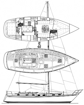
The interior layout is typical with a V-berth forward, the head (to starboard) and lockers (to port) which divide it from the main salon area which has a fold-up dining table with port and starboard settees. Aft and to starboard is a nav station with the electrical panel and to port is the galley with Adler-Barbour refrigeration, a gimbaled 3-burner gas stove with oven. The engine area is insulated and has great access. The private owner's stateroom aft has a queen size berth, hanging lockers, chest of drawers, and a private head with shower.
There are 14 opening ports (Beckson) and 4 large Atkins-Hoyle deck hatches (strong drop forged aluminum with 3/4" Lexan), one each over the v-berth and aft cabin and 2 over the salon area.
A U X I L A R Y
We believe that almost all, if not all Endeavour 40s were originally equipped with a Perkins 4-108 (50hp) auxiliary which is the most common diesel found on sailboats. We do see some boats in our database with Yanmars 4JH5, 4JH3, and a Westerbeke 63C but these are probably refits as the Perkins get replaced.
The diesel is fitted with a mechanical gearbox transmission.
The propeller shaft is made of 1-1/4" stainless steel and exits the hull through a stuffing box. It is supported at the inboard, or engine end, by the shaft coupling, and at the aft end by a cutlass bearing mounted in a stainless steel shaft log bolted to a fiberglass skeg immediately aft of the keel. The skeg is integrally
molded with the hull.
The standard propeller was a 17" x 17 2-blade prop or an optional 17" x 16 3-blade prop.
In the Perkins engine, a water pump draws water through the intake port, circulates it through a heat exchanger, where it is pumped in the muffler and overboard through the exhaust port. The salt water in
the heat exchanger lowers the temperature of the engine coolant circulated through the engine block by
means of the normal engine water pump.
E L E C T R I C A L . .S Y S T E M
Virtually all wiring is located high and accessable by removing panels from under the side decks. All wiring is 10 gauge stranded copper with crimp type connectors used at all junctions or terminals. All wiring is color coded with DC wiring as two wire and AC as three wire. Metallic fittings (through hulls, etc.) below the water line are electrically bonded together with 8 gauge copper wire and connected to the ships common ground.
The main electrical panel has on/off circuit brakers and a battery selector which serves as the master DC on/off switch. Shore power service is 30 amps.
The standard battery configuration on the Endeavour 40 consisted of two 12-volt batteries connected in parallel to allow single or combined use and charged from the stock 35 amp alternator.
|