E37 SLOOP OVERVIEW
DESIGNER:
Dennis Robbins,
Endeavour Yachts
(Robert Johnson: TM Cutter)
PRODUCTION: 1977-1983
HULLS: Approx 476
(Sloop, Cutter and Ketch)
E37 SPECIFICATIONS
LOA: 37'5"
LWL: 30'
BEAM: 11'7"
DRAFT: 4'6"
DSPL: 20,000lbs
BALLAST: 7,500lbs
DWL: 46' 0" (STAND)
SAIL AREA:
SLOOP (STAND): 580 sq ft
SLOOP (TM): 726 sq ft
MAIN:
SLOOP (STAND): 258 sq ft
SLOOP (TM): 312 sq ft
100% FT:
SLOOP (STAND): 322 sq ft
SLOOP (TM): 414 sq ft
I =
43' (STAND)
46' (TM)
J =
15' (STAND)
18' (TM)
P =
36' (STAND)
39' (TM)
E =
14' (STAND)
16' (TM)
See Rigging Specifications for specifics
HEADROOM: 6' 3"
BERTHS: 6
PLANS: A, B, AND C
FUEL: 55 gal (diesel)
WATER: 100 gal (hot/cold)
HOLDING TANK: 15 gal
E37 SLOOP STATISTICS
D/L RATIO: 331 (STAND)
(less than 100 = ULDB
100-200 = light,
200-300 = medium,
SA/D RATIO: 12.59 (STAND)
BAL/D RATIO: 38 (STAND)
LWL/BEAM: 2.59
CAPSIZE RATIO: 1.71
MOTION COMFORT: 36.43
(RANGE = 5 - 60: Higher number means more comfort in a sea)
HULL SPEED: 7.34 knt
PDF DOWNLOADS
E37 BROCHURES:
E37 Spec Sheet (1.5mb)
E37 Sloop Plan-B Owners Manual (512k)
E37 Sloop Sail Plan (292k)
E37 Cockpit Sole Plan (144k)
OTHER:
EDSON Steering System (228k)
PERKINS 4-108 Handbook (816k)
PERKINS 4-108 Parts Book (3.5mb)
PERKINS 4-108 Workshop Manual (8.9mb)
E37 REVIEWS:
E37 SEA Trial Review (1.3mb)
Used Boat Notebook Review

|
D E S I G N&H I S T O R Y
Encouraged by the success of the Endeavour 32, Endeavour began looking around for a sister ship. Looking for boats along the Miami River, Brooks and Valdes found an old abandoned Ray Creekmore design which the then in house designer Dennis Robbins modified. The 34ft design was cut in half, and 3 feet added to the midsection, and created the Endeavour 37. Introduced in 1977, 476 were sold until production ended in 1983. The boat was initially designed as a ketch but was also offered as a sloop and cutter. Some Endeavour 37s were built with an optional 3 foot bowsprit (ketch and cutter) that increased the area of the foretriangle. It also came with a short, a standard, and a tall mast. The larger foretriangle boats were 'reportedly' offered in response to owners asking for better sailing performance.
The Endeavour 37 interior was a "2 arrangement" design that was an innovative idea at the time. The dinette forward (Plan-A) was introduced first in 1977 and proved so popular that the more conventional interior (Plan-B) didn't enter production for well over a year later. A third interior layout (Plan-C) was also created, removing the chart table from the Plan-A version and making the aft cabin private.
John Brooks and Rob Valdes, having both been previously employed by Gulfstar, always had Gulfstar in their sights as a tagrget market, so it wasn't by accident that some of the signature design features that appeared in the Endeavour 37 were influenced by Gulfstar.
The early Endeavours (E32, E37, and E43) were simple, straight forward boats with outboard chainplates, short rigs, and strong, moderate hulls.
H U L L&D E C K
The hull of the Endeavour 37 is molded as a single unit of a combination of polyester resin and fiberglass woven roving and multi-directional chopped strand fiber (MCSF). The keel is molded integrally with the hull and the lead ballast is contained inside.
The exterior finish is a pigmented gelcoat molded onto the fiberglass. The boot and sheer stripe are also gelcoat molded permanently into the hull.
The deck and cockpit, like the hull, are molded as a single unit of a combination of polyester resin and fiberglass woven roving and MCSF. Plywood coring is incorporated between the layers of fiberglass in the cabin top, deck, seat, and cockpit sole areas to give additional stiffness. The non-skid finish is molded into the deck. All exterior deck surfaces are a pigmented gelcoat molded onto the fiberglass.
The joint between the hull and deck is one of the most important assembly steps in the construction of the E37. During assembly, the top integral hull flange is liberally coated with a combination adhesive/sealant. The deck is then lowered onto the hull and fastened in place with stainless steel bolts. When the bolts are tightened, the excess compound is forced into all the crevices and out the sides. The teak cap is then installed, bedded in a heavy layer of the same compound and secured in place, ensuring water tightness.
R U D D E R&S T E E R I N G
The rudder is molded as a single piece of solid high density foam with a protective skin of fiberglass and gelcoat finish. The foam material is of high strength structural grade providing exceptional toughness. The rudder post, molded integrally inside the rudder, is solid stainless steel, which is welded to a steel blade in the interior of the rudder.
Where the rudder post passes through the hull, water tightness is ensured y means f a stuffing box.
The pedestal steering system operates with stainless steel cables rotating a quadrant bolted and keyed to the rudder post. The cables run through guide sheaves to the pedestal where they are shackled to a stainless steel chain running over a sprocket on the steering wheel shaft.
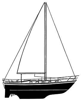
S P A R S&R I G G I N G
All spars (mast, booms, and spreaders) are extruded aluminum 6061-T6 alloy, with protective coating on all external surfaces. The main mast is stepped through the cabin roof onto the keel.
On the sloop the forestay attaches to the stem head fitting at the bow whereas some cutter and ketch versions place it at the foreward end of the bowsprit. This is fabricated of welded stainless steel backup plates and through bolted to the hull. All other stays and shrouds are attached to chainplates at the edge of the deck these chainplates are stainless steel straps through bolted to the hull. Additional fiberglass reinforcement is molded into the hull in all chainplate areas. Standing rigging is 1 x 19 stainless steel wire.
All standing rigging is attached to chainplates with adjustable turnbuckles that allow fine tuning of rigging tension.
All halyards were originally stainless steel wire rope with Dacron line tails to minimize stretch and reduce windage. All halyards are run externally to #8 Lewmar single-speed winches mounted on the mast. Sheets are led to #40 Lewmar self-tailing winches in the cockpit. Sheets are led outside through blocks on adjustable cars on tracks. The main sheet traveler is mounted in the cockpit aft of the companionway.
A bowsprit to extend the headstay, a bowpsrit as and anchor platform only, and a ketch rig were listed as factory options in April 1980.
I N T E R I O R
The interior of the E37 is built up from wood. A framework of floor timbers is constructed and placed in the bilge and heavily bonded in place with woven roving. A plywood sole is glued and screwed on top of these floor timbers and bonded to the hull all around the periphery with woven roving.
All timbers and plywood are saturated with polyester resin before assembly to seal all exposed wood.
The entire sole is covered with teak parquet flooring, bonded in place with waterproof adhesive. All bulkheads are bonded to the hull with two layers of woven roving on both sides. The interior is finished with varnished teak with soft white overheads.
All lockers are wood paneled, Formica counter tops, louvered Teak hanging locker doors, and teak drawer pulls.
The interior layout of the Plan-B has a V-berth forward, with set of drawers (starboard) and locker (port). The head with shower is to port and wet locker to starboard. The main salon area has a solid teak fold-up dining table. The port side settee pulls out to create a double berth, the starboard is a single. Aft and to port is a pilot berth, and navigation station. To starboard is a U-shaped galley which originally came with an icebox and either a gimbaled 3-burner alcohol or gas stove with oven. The electrical panel is located immediately under the companionway, and the stairs remove to allow access to the engine. A Plan-B with the dinette forward was the original layout, and about 6l Plan-C options were also built.
There are 10 opening ports with screens (Beckson), two large Atkins-Hoyle deck hatches (strong drop forged aluminum with 3/4" Lexan) and one smaller deck hatch aft of the Nav station.
A U X I L A R Y
The Perkins 4-108 by Detroit Diesel was the standard offering, along with a Warner hydraulic gearbox with 2.57:1 reduction. The propeller shaft is made of 1-1/4" stainless steel and exits the hull through a stuffing box. It is supported at the inboard, or engine end, by the shaft coupling, and at the aft end by a cutlass bearing in a cast bronze strut.
The standard propeller is a solid bronze 17 x 17 LH 2-blade prop; an optional 17 x 16 LH 3-blade prop was also available.
E L E C T R I C A LS Y S T E M
Virtually all wiring is located high and accessible by removing panels from under the side decks. All wiring is 10 gauge stranded copper with crimp type connectors used at all junctions or terminals. All wiring is color coded with DC wiring as two-wire and AC as three-wire. Metallic fittings (through hulls, etc.) below the water line are electrically bonded together with 8 gauge copper wire and connected to the ships common ground. The standard battery configuration consisted of two 12-volt batteries connected in parallel and are charged from the engine alternator.
|