| E35 OVERVIEW
DESIGNER: Bruce Kelley
PRODUCTION: 1983-1987
HULLS: Approx 300
E35 SPECIFICATIONS
LOA: 35'5"
LWL: 29'6"
BEAM: 12'2"
DRAFT: 4'11"
DSPL: 13,250lbs
BALLAST: 5,630lbs (internal lead)
DWL: 53' 10.75"
SAIL AREA: 671.5 sq ft
100% FT: 393.6 sq ft
MAIN: 282.75 sq ft
I = 50'
J = 15'10"
P = 43'6"
E = 13'
See Rigging Specifications for specifics
HEADROOM:
BERTHS: 6
FUEL: 33 gal (diesel)
WATER: 76 gal (hot/cold)
HOLDING TANK: 15 gal
E35 STATISTICS
D/L RATIO: 230
(less than 100 = ULDB
100-200 = light,
200-300 = medium,
+300 = heavy)
SA/D RATIO: 19.19
(14 = low, 22 = high)
BAL/D RATIO: 42.5
(33-45 is average, higher=more stablitiy)
LWL/BEAM: 2.42
(2.3=low, 3.0=high)
CAPSIZE RATIO: 2.06
(Less than 2.0 is prefered)
MOTION COMFORT: 23.28
(RANGE = 5 – 60: Higher number means more comfort in a sea)
HULL SPEED: 7.28 knt
PDF DOWNLOADS
E35 BROCHURES:
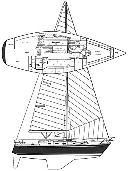
E35 Sail Plan
E35 Brochure
E35 REVIEW:
Bruce Kelly Review
Jack Horner Review
OTHER:
PERKINS 4-108 Handbook
PERKINS 4-108 Parts Book
PERKINS 4-108 Workshop Manual
|
D E S I G N &H I S T O R Y &H I S T O R Y
We currently don't have the design brief for the Endeavour 35 or any information on Bruce Kelley and his involvement in the design of the E35. However the E35 would seem to be part of the natural progression of introducing newer, updated models at Endeavour. At the time, production of the E32 had ended (1982) with the E33 replacing it (1983). Based on other historical information both the E33 and E35 were introduced in response to market demands for faster, better sailing boats, and the E35 would seem to fill the void of having a larger, updated design.
According the the Endeavour 35 brochure, Kelley gave the boat the proportions necessary to be very fast upwind while retaining the room below to accomodate a comfortable layout. Note the focus on upwind performance which would have signaled a philsophical shift away from the heavy shoal draft cruising boats more suited to reaching conditions.
H U L L&D E C K
The hull is molded as a single unit of a combination of polyester resin, fiberglass, and closed cell polyvinyl foam core. The keel is molded integrally with the hull and all ballast is contained inside.
The exterior finish is a pigmented gelcoat molded onto the fiberglass. The boot and sheer stripes are a sprayed coating of Imron.
The deck and cockpit, like the hull, are molded as a single unit of a combination of polyester resin and fiberglass woven roving and MCSF. Closed cell polyvinyl and plywood coring is incorporated between layers of fiberglass in the cabin top, deck, seat, and cockpit sole areas to give additional stiffness. All exterior deck surfaces area pigmented gelcoat molded onto the fiberglass.
The hull-to-deck joint is an integral 'flange' type, which during assembly, is liberally coated with a combination adhesive/sealant. The deck is then lowered onto the hull and fastened in place with stainless steel thru-bolts. When the bolts are tightened, the excess compound is forced into all the crevaces and out the sides. The teak cap is then installed, bedded in a heavy layer of the same compound and secured in place, doubly insuring water tightness.
All ballast is internally mounted inside the keel, which is molded integrally with the hull. Cast pieces of lead are placed in the hull, encapsulated in polyester bonding resin, and then covered with a layer of woven roving to form a fiberglass cap. When finished, the ballast becomes a structural part of the hull.
R U D D E R&S T E E R I N G
The rudder is molded as a single piece of solid high density foam with a protective skin of fiberglass and a gelcoat finish. The foam materila is of high strength structural grade and has exceptional toughness. The rudder post, molded integrally with the rudder, is solid stainless steel, which is welded to a steel blade in the interior of the rudder. Where the rudder post passes through the hull, water tightness is ensured by means of a stuffing box.
The pedestal steering system operates with stainless steel cables rotating a radial quadrant bolted and keyed to the rudder post.
S P A R S&R I G G I N G
All spars (mast, boom, and spreaders) are extruded aluminum 6061-T6 alloy, with a protective coating an all external surfaces. The mast on the E-35 is stepped through the cabin roof onto the keel. The masts and booms we've seen on the E35 were Kenyon double spreader masts, and booms with single or double reefing capabilities and sheeting about mid boom with the traveler spaning the coach roof.
The standing rigging is made of stainless steel wire. The forestay attaches to the stem head fitting at the bow. This is fabricated of welded stainless steel and through bolted to the hull with back-up plates. All stays and shrouds are attached to stainless steel chainplates (with adjustable turnbuckles) at the edge of the deck and are through bolted to heavy structural bulkheads. The forestay, backstay, and upper and lower shrouds are made of 9/32" stainless steel wire.
I N T E R I O R
A U X I L A R Y
E L E C T R I C A L . .S Y S T E M
|