ALCOHOL TO PROPANE STOVE REFIT
Part 3 -- The Installation
Date: June 14, 1999
From: Paul Uhl endvr32@endeavourowners.com
 THE STOVE
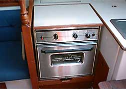
Removal was easy. Disconnect the old alcohol fuel line and seal it off so that it doesn't leak, lift up the old stove and heave overboard. The width of new stove was actually 1-inch narrower than the old "Galley Made" so I made 1/2" plywood shims for each side, and just a bit larger than the new wall mounted hangers that came with the stove. Critical measurements are of course the height, but also proper depth! There is very little room for error on this last dimension as 1) too far back and the stove pitches into the counter top behind, and 2) too far forward and it catches on the kick base and will not allow the bin under the sink to open. Be very careful in determining this measurement. Since I planned to reuse the countertop insert for the stove on the new stove, I determined my height with this item in place. For measuring the depth you might make a template of the side of the stove allowing for the insert. Measure twice, drill once! I used machine bolts with self locking nuts on the forward wood side, and wood screws for the aft fiberglass side.
Before I made the final hanging of the stove, I connected the 20' long propane hose assembly and lead it through the same cutout that the alcohol fuel line came through.
Lastly, if you have the original block that the locking mechanism for the original stove locks into, remove it from the partition wall, place the new bolt on the stove into the opening on the old block, and position until the stove top is level. Mark the new location for the block and remount. You may have to drill a new hole in the old block for the lock on the new stove as the post that is attached to the partion wall prevented me from bringing the block far enough forward for for the stove to be level.
 THE PROPANE CONTROL HEAD AND SENSOR
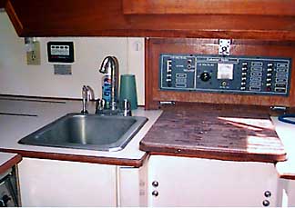
Although not a hard job, it was a bit difficult to pull the wires for the control head. As you can see in the picture to the right, I decided to mount the control head on the aft cabin wall. It's easily accessible, easily viewed and monitored, and close to the electrical panel. The hard part was pulling the wires up, behind the fiberglass wall that it is attached to as the space between it and the fibergalss that makes up the backside of the cockpit is very tight. I determined my location and made a cutout about 3/4" square centered behind the control head (mark the screw holes for mounting the control head).
Directly above the electrical panel spanning the underside of the bridgedeck, there is a removable panel . This area, once the panel is removed, reveals other ships' wiring leading to the electrical panel. I removed the panel so that I could run the wires from the control head behind, up, and over the fibergalss wall. Once the wires were pulled behind the wall, I could then easily run them with the other house wires under the bridgedeck and drop down to the back side of the electrical panel area. I used a long screw driver to 'pry' the wall away from, and force more space between the aft fiberglass wall and the backside of the cockpit. I then replaced the panel and mounted the control head to the aft wall.
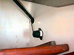
Next I mounted the remote sensor under the stove (propane is heavier than air) and fed the sensor wires through the same hole as the fuel line, and lead them up to the control head wires. I attached the sensor wires to the boat using wiring cables to keep them from flopping about. I connected the ground and used one of the in line fuse holders to connect the control head to the hot side of an unused breaker on the panel. I used water proof ring terminals to attach the ends of the + and - to the breaker and used heat shrink tubing for all my wire connections. This to strengthen them and seal out moisture.
 Next, I ran a pair of 18 gauge wires from the control head along with the propane hose to the aft port fuel locker for later connection to the solenoid. At critical points I wrapped the propane hose with pipe insulation to reduce wear, etc. and used wiring cables to attach it to the boat. I kept my run inboard and as short as possible.

 FUEL LOCKER
Since the locker already had an overboard drain, all I needed to do was to make two holes. One for the straight-through to seal the propane hose from the rest of the boat, and a second to lead the solenoid wires into the locker. I made these two holes on the aft wall, near the top and as far to the outboard side as possible. This to allow easy access from below, and to allow the extra hose and wiring to coil up on the outboard wall. Note: since the locker has a small diameter, you need a small (short) drill to make the holes, otherwise you end up drilling them on an angle.
Next, I installed the straight-through using caulk to bed it, let it set and tighten. After this dried, I pulled the propane hose through the straight-through and the wires through the other hole, caulking the electrical wires. When that dried, I tighten the straight-through around the propane hose.
Last, I purchased a rubber cockpit interlocking grate and cut it to fit the sole of the fuel locker. I did this to keep the propane tank from resting on the bottom of the locker, and to allow drainage under the tank.
 TANK, REGULATOR, SOLENOID
I'm sure all of us have a type of project that, no matter how hard we try, never seems to go right. Maybe for you it's electricity or carpentry, but for me it's plumbing. I always seem to be missing a part or two, have the wrong part, or need another part and have to go get it. Sometimes it's just trying to find the place that has it. Ever try describing a 'thing-a ma-bob' over the phone?
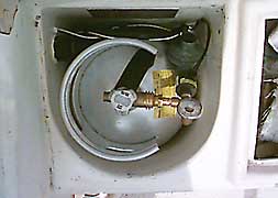
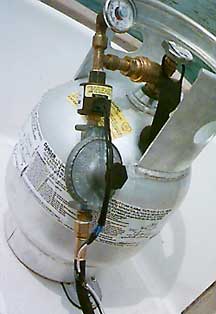
The first issue, although the tank fits in the locker, is how to fit the gauge, regulator, solenoid, and miscellaneous fitting into this limited space. And after much trial and error, did it! I'll try to explain but a picture is worth a thousand words, and the one on the right says it all.
When I purchased the regulator, it came with a T-fitting and pressure gauge attached. However the configuration came with the pressure gauge on the shaft portion of the T. I switched it to the other end of the straight-through portion with a 90 degree fitting and attached the POL tank fitting to the shaft portion of the T (see picture), thus shortening the assembly. Next I attached the solenoid to the T-fitting making sure that the gas flow direction was correct, and attached a male flare adapter (1/4" NPT x 3/8" male flare) to the exiting end of the solenoid. The regulator then attaches to this. On the low pressure side of the regulator, I attached a 3/8" flare x 3/8" pipe fitting and connected the propane hose. Lastly, I connected the solenoid wiring and sealed the connection with heat shrink tubing to strengthen the connection, and seal out moisture.
As you can see I've angled all assembly downwards slightly rotated the regulator (hard to see) so that it fit as snug to the tank as possible. It (just) fit like a glove.
TESTING
Now with everything connected and installed I began my testing procedure. Turning on the tank I tested the fittings with a 50/50 mixture of dish soap and water. Satisfied there were no leaks before the solenoid, I turned the tank off and ran the control head through it's initialization. Once it was initialized and operating, I turned the gas back on and switched the solenoid. I tested the remaining fittings at the tank, bleed the stove, and checked the connection on the stove for leaks.
Well there you have it! The hardest part was figuring it out--especially getting the tank and fittings into the locker and I hope I've made that part easier for you.
Part 2 -- Specifying the System Part 4 -- Other Owners Comments
![]()